


Document Actions
gvSIG-Desktop 1.10. User Manual
- Alphanumeric editing
- Introduction
- Editing session for an 'internal' table.
- Editing session for an 'external' table.
- Managing fields
- Editing a layer's table of attributes
- Field Calculator
- Introduction
- Accessing gvSIG's field calculator
- Introduction example
- Description of the 'Field Calculator'
- Agregar información geomítrica a la capa
- Importar campos de una tabla a otra
Alphanumeric editing
Introduction
A table is part of a data base. It is made up of rows or records and columns or fields which contain the alphanumeric information needed to characterise the elements (polygons, lines or points) which make up the theme maps, cartography in general and graphs. The rows represent elements or objects and the columns represent the variables or attributes associated with each element.
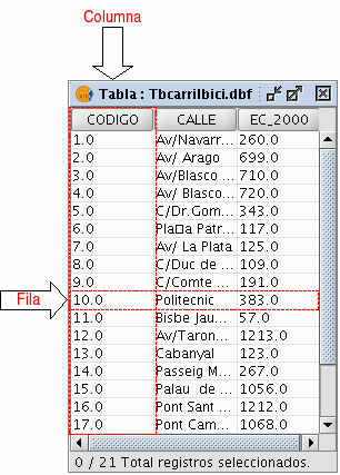
In general terms, there are two types of tables; “internal” tables which are typical of an information layer and are found in the same file and “external” tables which can be added to a gvSIG project. Each element (point, line or polygon) of a layer only has one record in that layer’s table of attributes.
Editing session for an 'internal' table.
Open a “View” and add the layer you wish to work with.
Remember that to start an alphanumeric editing process in gvSIG, you must put the layer you are working with in editing mode. In order to do this, select the layer in the ToC, go to the “Layer” menu and select “Start edition”. Select the “See table of attributes” button

or go to the “Layer” menu and select “See table of attributes”.
The table associated with the layer will be automatically added to the project.
If you go to the “Project Manager” and select the “Tables” type of document, you can check that the table shown in the view is included as a separate document in the project.
To finish the table editing session, go to the “Layer” menu and select “Finish edition”. When the session finishes a message appears asking if you would like to save the changes. Click on “Yes” to save all the changes made in the table.
Editing session for an 'external' table.
- Go to the gvSIG’s “Project Manager”, and select the “Tables” type of document.
- Click on “New”.
- Click on “Add” and open the table you wish to edit.
- When you click on “Open” the table is displayed automatically on the screen.
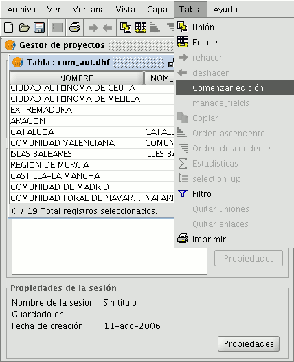
- Go to the “Table” menu and select “Start edition”.
Managing fields
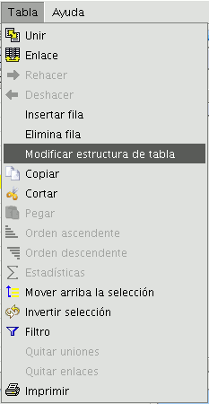
This tool allows you to add, delete or rename fields. To access this tool, go to the “Table” menu and select “Manage fields”.
(An error occurs when you try to change the structure of a table hosted in a postgresql data base above version 7.4. To modify the structure, use a suitable data base manager).
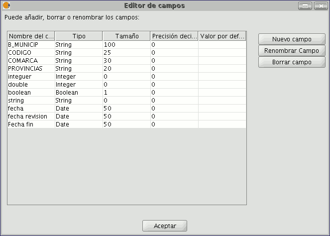
When the menu option is selected, a window appears in which the fields of the selected table and the buttons to create a new field or delete or rename an existing field are included.
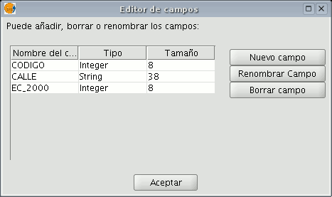
If you click on “New field”, a new window appears in which some of the properties of the new field to be added to the table can be configured.
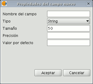
Field name: Enter the name of the new field. Type: If you click on the arrow on the right, a pull-down menu appears in which the type of field data (string, double...) can be configured.
Length: Indicate the required length of the field. (The max. length of a string field is 254 charecters).
Precision: Indicates the number of decimals a numerical field must have (only for numerical type fields).
Default value: Indicates the default value for the field when no specific value is defined in the table.
If you wish to use the delete tool (“Delete field”) and the renaming tool (“Rename field”), simply select the field to be modified and click on the corresponding button.
Editing a layer's table of attributes
Adding a record
To add a new record to a table associated with a layer, a graphic element must be inserted. When an element is added to the associated table a new blank record appears.
Enter the data for the new entity and press “Enter”.
N.B.: Remember that if you wish to delete the selection, you can go to the tool bar and click on “Clear selection” or you can use the menu bar by clicking on the “Layer” menu and then on “Clear selection”.

N.B.: You can create a new layer with the elements selected in the table if you wish. To do so, close the table, go to the menu bar and click on the “Layer” option and then on “Export to ...”. Then select the format you wish to create the new layer with.
Modifying a record
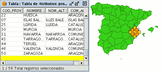
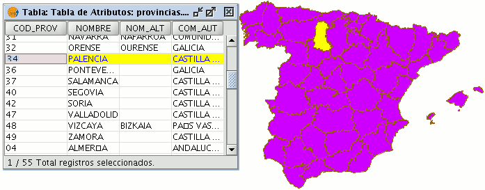
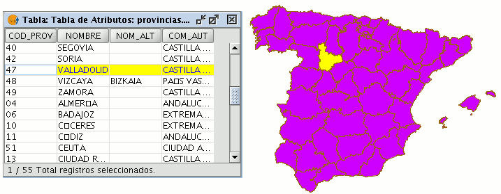
To modify the data of a layer element saved in the table, select the element whose data you wish to modify. The record that corresponds to the selected graphic element is highlighted in yellow in the table of attributes.
Left click on the cell in which the record to be modified is located. The record changes and a cursor appears to indicate that the data can be input.

Removing a record
To remove a record from the table, you must first select the record.
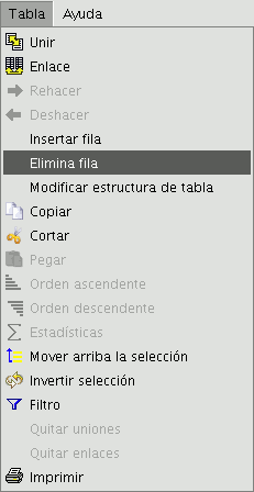
Go to the “Table” menu and select “Remove row”.
The selected record is deleted from the table and the associated graphic element disappears from the view.
Field Calculator
Introduction
gvSIG’s field calculator allows you to perform different types of calculations on the fields of a table (for example calculate areas, perimeters, convert the data in a field from degrees to radians, etc).
Accessing gvSIG's field calculator
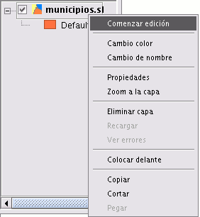
To access the field calculator, you must first start an editing session in gvSIG. If you wish to activate the edition of a layer loaded in a view, go to the layer’s contextual menu and select “Start edition”.
If you wish to edit a recently-loaded table, go to the “Table” menu and select “Start edition”.

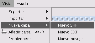
If you decide to use the field calculator on a “New layer” (for example New shp) which you are going to create (remember that to access this option you must go to the “View” menu and select the “New layer” option), the layer will automatically appear in editing mode when inserted in the view.
Once you have started an editing session, activate the table of attributes on which the operations are going to be performed and select one of the fields (by clicking on the field heading). The following button will then be activated in the tool bar:

This will allow you to access the field calculator.
NB. The first time you open the field calculator in a new gvSIG session, a warning window appears to inform you that the calculator is “Loading operators”. Once this process has finished, the window which allows you to perform operations with the various fields appears.
Introduction example
“Field calculator” Let us look at a simple example to explain how the field calculator works.
In order to work out the area of a series of plots in a layer we have created:
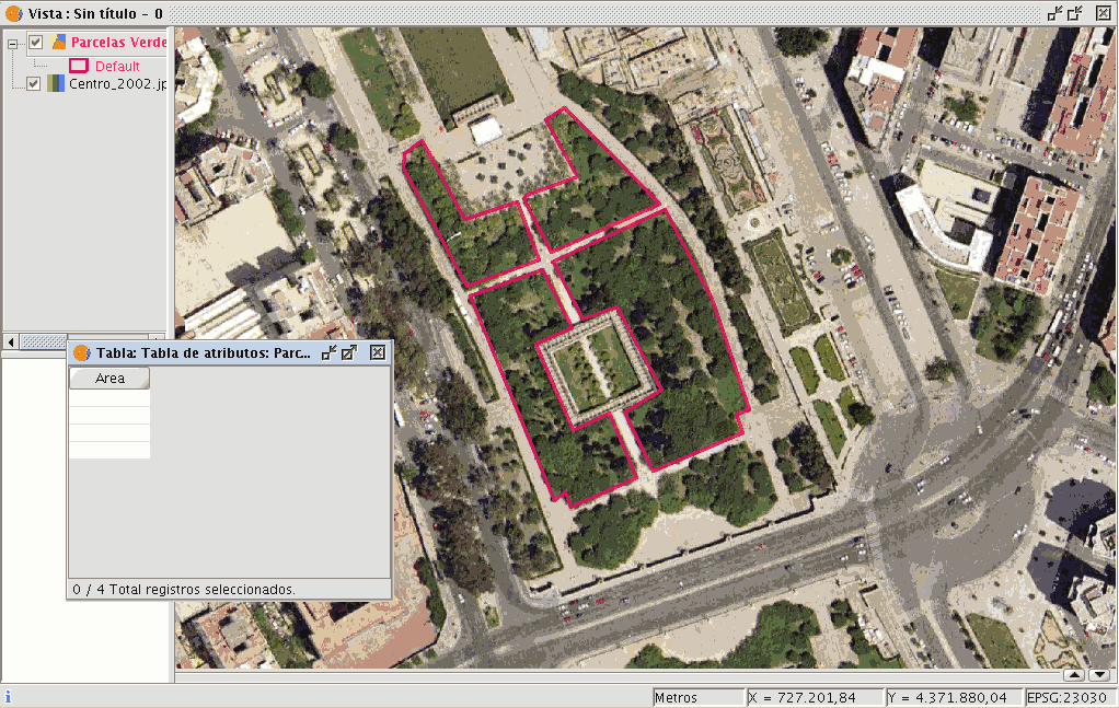
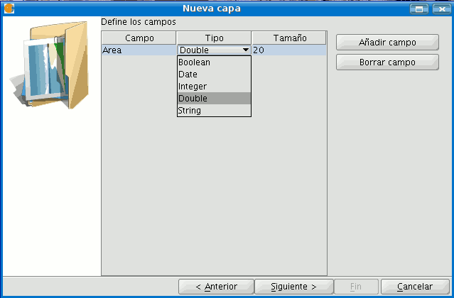
First, open a gvSIG view and load an orthophoto which will be used as a base to determine the location of the plots. Next, select the tool in order to create a new shp file (View/New layer/SHP).
Select a “Polygon” type layer, click on the “Next” option and then create a “Double” type field called “Area”, leaving the default value at 20.

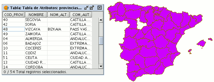
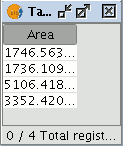
Draw four plots on the orthophoto using the “Insert polyline” tool selected from the tool bar. The image below shows that a record for each of the plots has been created in the table.
Select the field from the table and activate the field calculator.

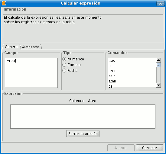
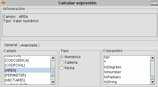
The following information appears in the “General” tab:
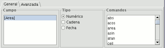
“Field”. This contains the various different fields which comprise the table being worked on.
“Type” of field selected. Access to different commands depends on the type of field.
“Commands” which can be used in the calculations.
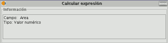
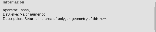
The “Information” section shows that:
If the “area” command has been selected in the “General” tab, a brief description will be displayed in the information window.

If the “area” command has been selected in the “General” tab, the information window returns a message with information on the field type (remember that when designing the “area” shape, a Double type numeric field was created in which the area will be calculated).
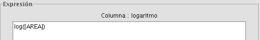
The “Expression" area displays the name of the column on which the calculation is being performed and a text box for the calculation sentence to be used.
In this case, the sentence included in the expression section is simple (no parameters are required as they are in other expressions which shall be explained later on).
To sum up and conclude this example, once the “area” command has been selected, click on “Ok” and the field created in the table will automatically be filled with the area values of each of the polygons drawn.
Description of the 'Field Calculator'
Introduction

The field calculator window has three different sections.
Information
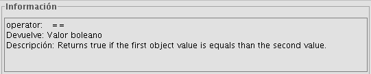
The Information section provides information about the type of field and the commands selected in the “General” tab.
The following information can be found in this section:
- “Operator" = This indicates the command selected and the expression which allows it to be executed.
Example: In this case the command we wish to use is “log”, which allows us to calculate the logarithm of a field with a numerical value.
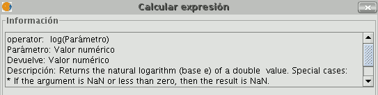
The “log (Parameter)” operator indicates that, for example, in order to obtain the logarithm of a field which contains the area data of a plot shp, the word “Parameter” must be replaced by the field we wish to obtain the logarithm of. As a result, the expression will be as follows: log([AREA])
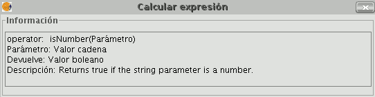
- "Parameter" = This can be one of three different field types which must be entered in the expression box in order to perform the calculation.
- Numerical value: a String, Double or integer type field must be entered.
- String value: A String type field must be entered.
- Date value: A date type field must be entered.
NB. If a table field is selected in the “Field” section of the field calculator, the information window indicates what type of data it is.
NB. In order to input parameters into the “Expression” text box, either double click on the name of the field from the list of fields in the General tab or type in the name of the field, in which case the String expressions input must be placed in inverted commas.
- "Return" = This indicates the type of data obtained as a result of the calculations.
Numerical Value = The result must be String, Double or integer type field data.
NB. If a String field type has been selected, it should be noted that this field type uses string values. If we add two String fields to another String field, the final result is a string and not the result of the operation (for example: 2+2 = 22, not 4).
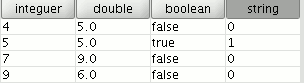
Boolean Value = A Boolean value returns a true/false answer to a question. If the result of the question is in a numerical field, it would therefore be either “1/0” depending on whether the reply was true or false. Let us look at an example:
We wish to know if there are records in a field which are the same as those in another field. The command which allows us to find this out “==”
If we type the following sentence: [integer] == [double] (double and integer being the names of two fields, each with numerical values), the response according to the type of target field (Boolean or String) can be seen in the image below:
- Date Value: The result must be in a Date type field.
NB. If a new layer is created in a gvSIG view (View menu / New layer), the wizard for this action allows you to specify the “Type of field” on which calculations are going to be performed.
If you are working with a layer and wish to know the field type, simply start a layer editing session, go to the “Table” menu and select “Manage fields”.
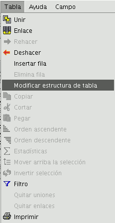
This opens a window called the “Field manager”, which allows the fields of a table to be created, renamed or deleted. It can also be used to confirm the field type.
General / Advanced Tabs
- General: This provides information about:
- "Fields": The text box shows all the fields of the table being worked on.
- "Type": Access to commands depends on which check box is activated.
- "Commands": These are the operators which allow expressions to be constructed to perform the calculations required.
- Advanced: A search box may be opened to look for an expression saved in a file.
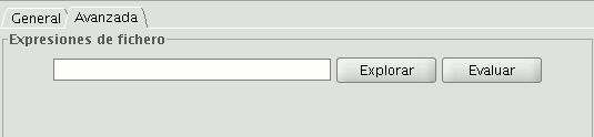
Once the file has been selected, click on the “Evaluate” button to find out whether the expression is correct or not.
NB. The expressions must be written in Python programming language.
'Expression' Section
The name of the field the results of the calculations of the expressions entered in the text box appear in is next to the “Column” text.
NB. The expressions are only calculated on the records selected in the table (if no records have been selected, the calculation is performed on all the records in the selected field).
Agregar información geomítrica a la capa
In gvSIG, the Add geometric info tool is available when there are visible vector layers in the active View.
| Icon | Description |
|---|---|
 |
Add geometric info tool enabled if there are visible vector layers in the current view. |
 |
Add geometric info tool disabled if there are no visible vector layers in the current view. |
With this tool you can select which geometric properties to calculate for a visible vector layer in the current view, and then save these properties in the layer itself. The information can be saved in either new or existing fields in the layer's attribute table.
Once the above condition is met (i.e. a visible vector layer in the active View), the tool is available:
Via the menu: Layer → Add geometric info
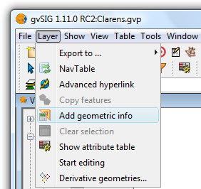
Selecting the Add geometric info tool from the menu
Selecting the tool displays a dialog where the attributes to be added can be selected:
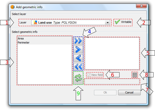
Add geometric information
1. Drop-down list for selecting vector layers. Lists the layers in the order that they appear in the TOC of the active view. The following information is shown:
- Postion of the layer in the TOC: displays various icons such as the layer grouping icon
 . The last icon always indicates a vector layer.
 - Name of the layer.
- Type of geometry of the layer: five types of layer geometries are supported: point, line, polygon, multipoint, and multi (which may contain any of the above).
2. Layer information writable. Indicates whether changes can be saved to the selected layer:
| Icon | Mode |
|---|---|
 |
Yes, changes can be saved. In this case the attributes to be added can be selected. |
 |
No, changes can't be saved. The tool will not list any attributes. |
3. List of geometric attributes. List of attributes of the geometry of the layer. These depend on the type of layer:
- Point layer:
- X coordinate
- Y coordinate
- Z coordinate
- Line layer:
- Length of the line
- Polygon layer:
- Perimeter of the polygon
- Area of the polygon
- Multipoint Layer:
- Number of points that make up the geometry
- Multi geometry layers: any of the above.
The geometric attribute will be associated with one type of geometry, which is identified by the icon on the left:
| Icon | Geometry type |
|---|---|
 |
The attribute is characteristic of point geometries. |
 |
The attribute is characteristic of multipoint geometries. |
 |
The attribute is characteristic of line geometries. |
 |
The attribute is characteristic of polygon geometries. |
4. Selection buttons. Allow attributes to be added to, or removed from, the list of geometry attributes to be calculated and saved for the vector layer.
| Icon | Option |
|---|---|
 |
Add all the geometric attributes to the list. |
 |
Add the selected geometric attributes to the list. |
 |
Remove the selected geometric attributes from the list. |
 |
Remove all the geometric attributes from the list. |
5. List of added geometric attributes. List of layer geometry attributes to be calculated and added.
Clicking on any of the attributes in this list enables the controls that allow the field to be renamed.
6. New field. This checkbox indicates whether the attribute is added as a new field, or as an update to an existing field in the vector layer.
 By default, every attribute is added as a new field.
7. Field name. New fields can have any name. Otherwise, select a field to update.
 The length of the field names is limited.
It is possible that the layer's alphanumeric encoding does not support some characters of the current language.
8. Save field settings. If the checkbox field is changed, or if another field name is specified, the changes can be saved by pressing this button.
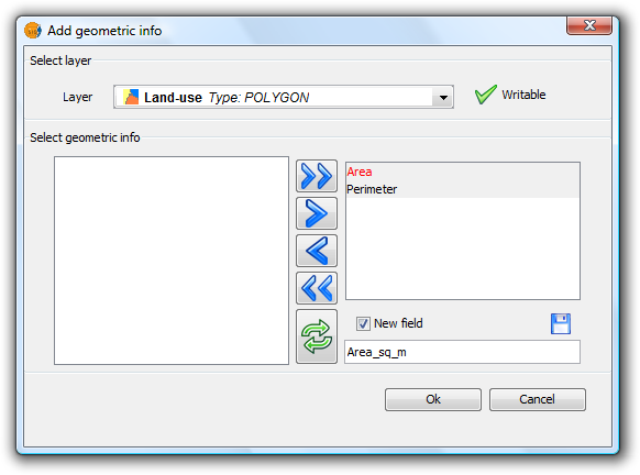
Add geometric information
9. Reset. Resets the dialog by reloading the current View's visible vector layers, and by removing any selected attributes and their settings.
Once all the attributes have been selected, click the Ok button to start the process and display a progress bar.
Clicking the Cancel button, on the other hand, will terminate the tool.
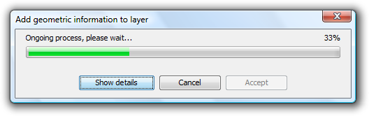
Progress of the Add geometric information process
- Progress bar: percentage of process completed.
- Show/Hide Details: show or hide the steps that have been completed.
- Cancel: Stops the process.
In the event of a serious problem, the process is terminated and an error message is displayed:
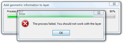
Error message
If the process completes successfully, the Accept button is enabled and the tool can be closed.
It is possible to view the steps that were performed by clicking the Show Details button in the dialog:
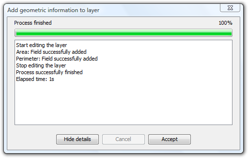
List of steps performed in adding geometric information
Do not use the gvSIG interface while the process is in progress as this can produce inconsistent data states, and even errors.
It should be noted that gvSIG currently adds the areas and perimeters of islands to that of the surrounding geometry.
EXAMPLE
Following the steps described in paragraph 5:
- A gvSIG project containing a view with a vector layer is loaded.
- The Add geometric information tool is loaded.
- The layer contains polygons so Area and Perimeter attributes are available.
- These two attributes are added as new fields with default names (Because of the shape encoding support the process removes accents and any occurrences of characters such as ç, Ç, ñ, Ñ).
- Click the OK button.
- Start and end the process successfully. Attributes are added as new fields in the selected vector layer.
- Click the Accept button to close the progress dialog.
- Open the layer's attribute table and move the horizontal scroll bar to the right to view the newly added attributes.
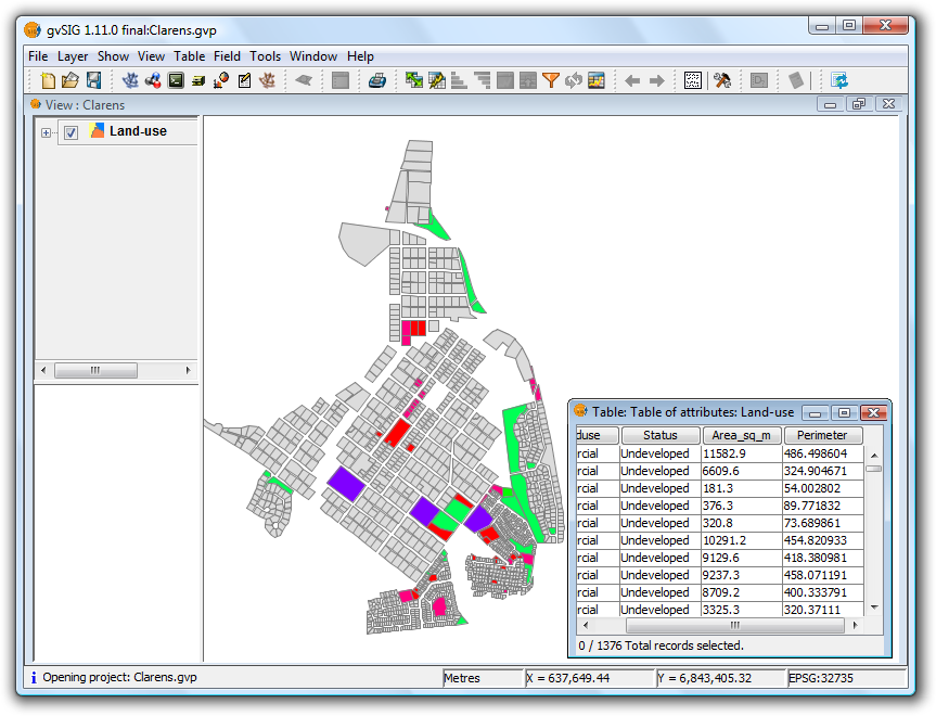
Example showing the calculated geometric information
Importar campos de una tabla a otra
The "Import fields" tool is used to import fields from one table to another. Both tables must have a common field.
In order to access the tool from the Table / Import fields menu, first open the table into which the fields are to be imported.
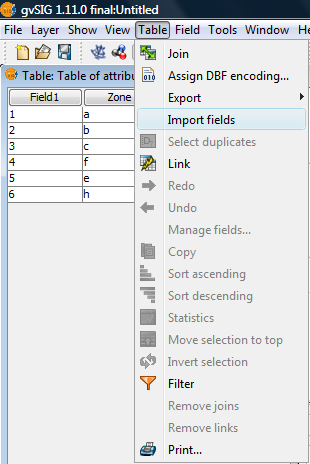
Menu path to the tool
Clicking on "Import fields" opens the following dialog:
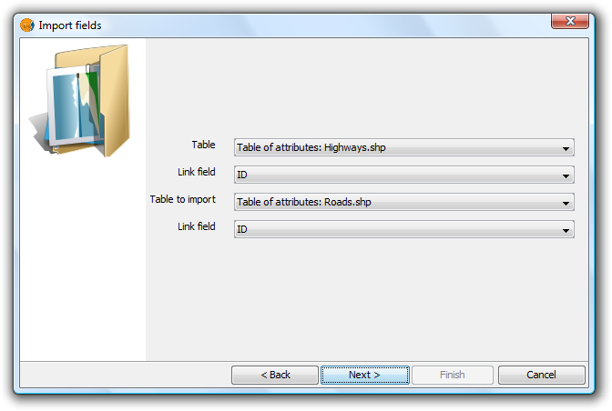
Tool dialog
Follow these steps to perform the import:
- First specify the table on which to do the import. The drop-down list only shows the table that is active.
- Then enter the field on which to make the join. This is a field that both tables have in common.
- Next indicate the table to be imported.
- Finally indicate the common field in this second table that will be used to perform the import.
Click the "Next" button and from the dialog shown below select the fields to import.
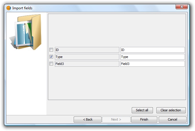
Final step of the tool
Click on the "Finish" button and check that the imported fields have been added to the end of the active table.


